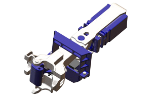
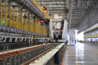
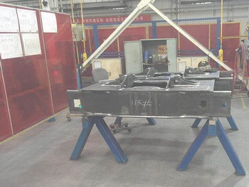
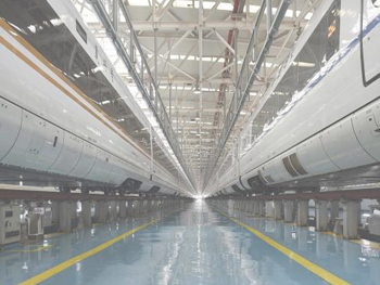
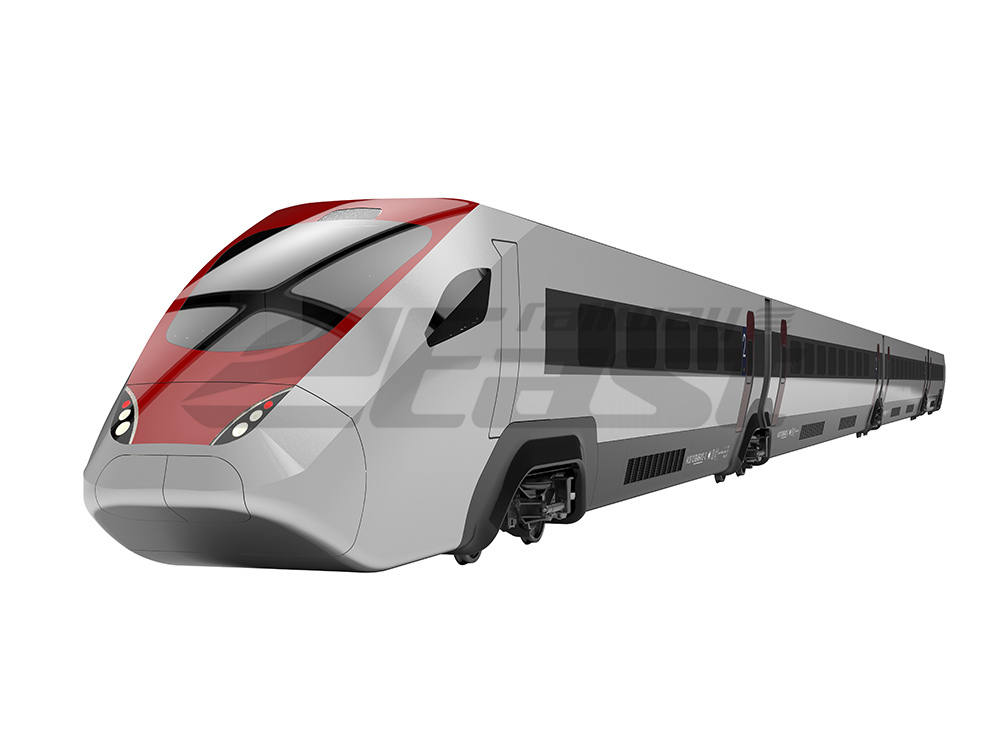
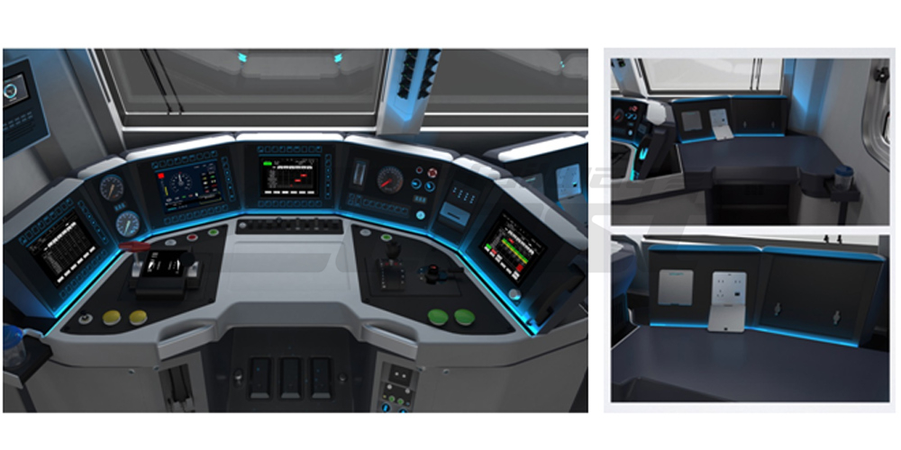
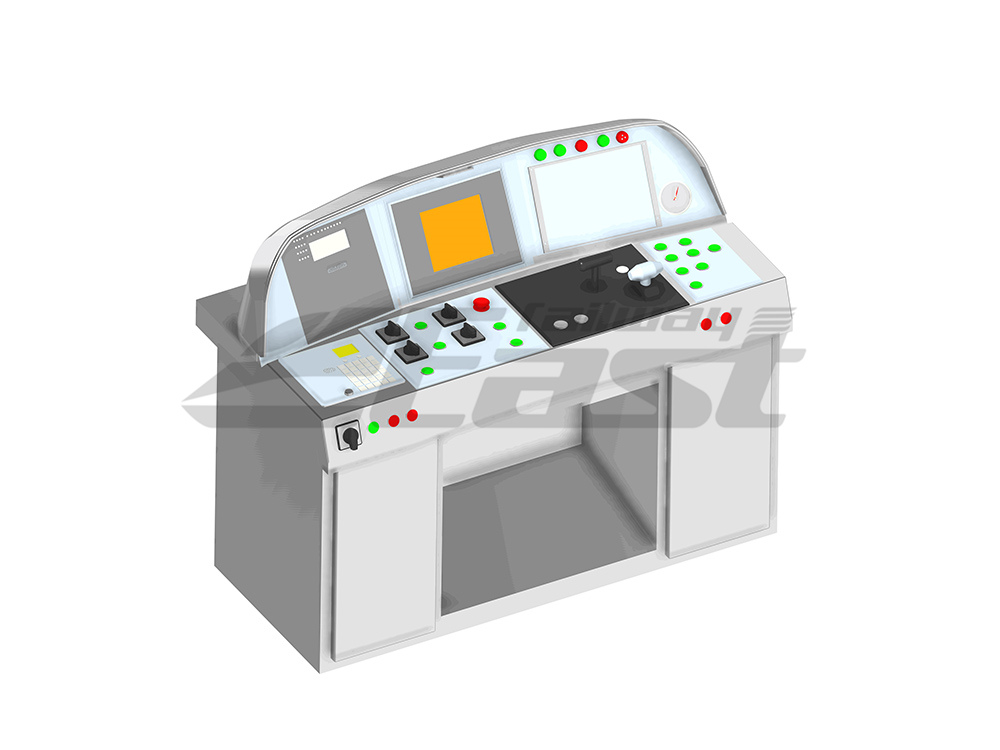
The main operations of the cab include control of the train's traction, braking, air conditioning, door and broadcast, while monitoring the running status of the train.
》Safety, overall structural compression resistance, high flexural strength
》Minimize hazards and set up escape facilities
》Compliant with ergonomic design principles, environmental related colors, lighting, ventilation, air conditioning equipment, noise, etc.
》Reduce driver fatigue and improve comfort;easy to operate.
》The visibility of the vehicle exterior is good and the viewable range is widely.
>It usually consists of equipment bay, operating area (drive deck), electrical cabinets, etc.
>The equipment compartment is mainly equipped with equipment that is not operated frequently.
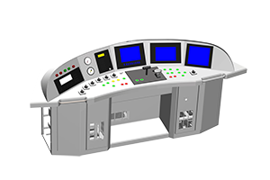
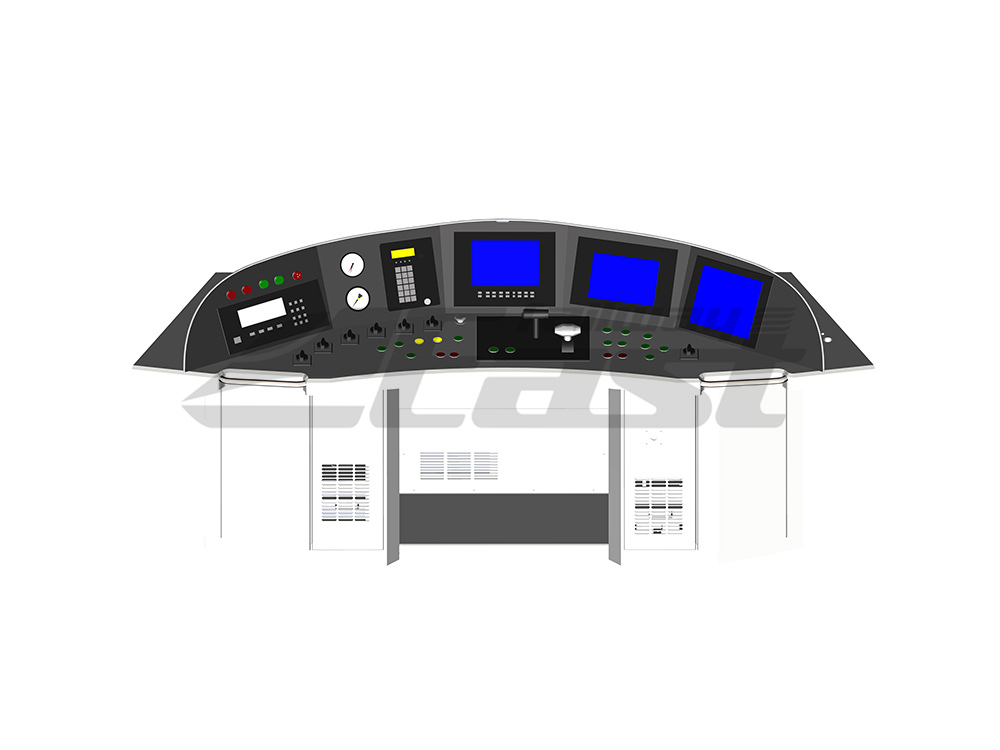
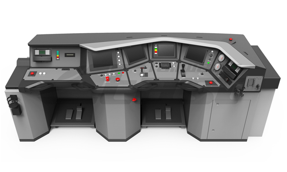
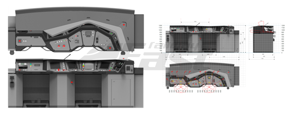
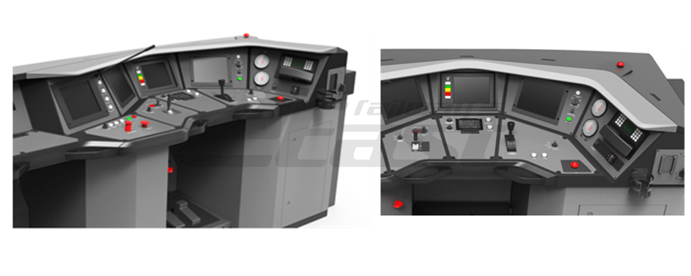
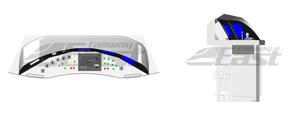
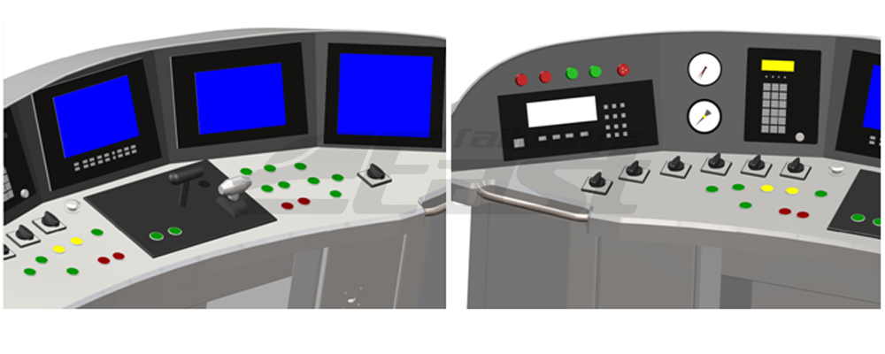
>The operator area is an important control component of the train, and all equipment that drives the train and obtains operational status information is concentrated here.The operation area is mainly divided into three parts, the instrument panel, the operation table, and the lower cabinet.
>Electrical cabinets are generally concentrated on the lower part of the driver's counter, on both sides, and on the rear of the driver.
Driver cab electrical equipment mainly includes driver desk, control panel cabinet, cab lighting, cab electric heater, headlights, wiper, electric glass, sunshade, terminal display, left/right screen, car radio, broadcastSystem, monitoring system, CCTV system, train automatic control system, train protection system, etc.
These electrical equipment, passenger indoor electrical equipment and under-car electrical equipment jointly complete the traction, braking, door opening, air conditioning, lighting, broadcasting, wireless communication, emergency intercom, TV monitoring and automatic control of the train.And the driver's countertop concentrates most of the functions related to driving operations.
TB/T 3491 Design PecificationOf EMU’s Cab
1. Structural safety requirements
1.1 Measures against destructive external forces
1.1.1 Under the condition of satisfying the driver's vision, the driver's seat position should be as high as possible to avoid external damage to the driver.
1.1.2 The cab should be securely built into the main frame of the tractor unit to ensure that any deformation caused by the impact occurs in front of or under the cab.
1.1.3 The structure of the cab should be able to withstand the specified pressure and should not cause permanent deformation.
Position | Pressure on the cab | Demand |
Frame under the windshield | 300KN | Evenly distributed |
Buffer beam level | 1500KN | Centerline of the coupler |
1.2 Measures to prevent the inertia of the internal equipment of the vehicle
1.2.1 The equipment inside the driver cab should be designed to meet the needs of the staff when they are not affected by sharp edges, protruding objects, etc.
1.2.2 The design of the driver cab indoor installation equipment and other components shall be fixed to meet the acceleration of the driver's cab at least 3g under the impact of the front.
1.3 Prevent other sources of danger
1.3.1 The driver's cab should not have any equipment that may pose a hazard to the staff (explosion, fire, electric shock or toxic steam, etc.)
1.3.2 Metal and unpowered components installed in the vehicle should be connected to the vehicle and grounded properly.
1.4 Set emergency exit
1.4.1 The cab should have at least one door or access that allows the staff to easily reach the longitudinal corridor leading to the other end of the vehicle in an emergency.
1.4.2 Staff should be able to safely and quickly evacuate the driver's cab and evacuate at least 2m.
2. Seat arrangement
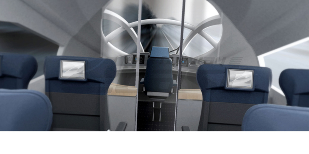
2.1 The driver's seat should be arranged in such a way that the driver sits facing the front track.
2.2 At least one driver's seat and another auxiliary seat.The seat can be adapted to the adult body size specified in GB/T 10000 and provides good support.With weight adjustment function, front and rear adjustment function, left and right rotation function, high multi-range adjustment function.
3. Partition door
A dedicated door is provided between the driver's cab and the passenger car, and the clear dimension is not less than 1724mmx452mm.
4. 扶手 Handrail
Handrails should be provided on both sides of the side door of the driver's cab.The distance from the lower end to the upper end of the handrail should not exceed 1250mm; the distance from the top of the handrail to the floor of the driver's cab should not be less than 1200mm.
5. Floor
The floor is non-slip, flat and easy to clean.
6. Driver’s window
6.1 The windshield size ensures that the driver can correctly observe the track and (visual) signals
6.2 The position design of all windows should refer to external visual signals and internal light sources, so that the driver is not misdirected by reflection or inconvenience caused by reflection in normal working position.
6.3 The windshield is made of colorless transparent safety glass with defrosting, defogging and antifreeze functions. Glare should not affect the operation.
6.4 The side window meets at least the clear dimension of 500mm x 400mm, ensuring that the driver can withdraw from the side window in an emergency.
6.5 Use safety glass and should not change the signal color.
7. illumination
7.1 Entrances, exits and evacuations should be easily identifiable during the day and emergency signs should have a luminous function.
7.2 All indicators are designed to be properly read under natural light or artificial lighting conditions. For normal working conditions, the indicator light should not cause adverse reflections in the cab window.
8. Air condition
8.1 Each door and window is completely sealed
8.2 The air condition has a temperature regulation function, and during operation, a small positive air pressure is allowed inside.
8.3 Ensure that the fresh air flow rate meets 30m³/(h. person), the driver can adjust the airflow, and the head airflow does not exceed 0.3m/s.
8.4 In the event of an air conditioning failure, there should be emergency ventilation measures.
9. Safety equipment
9.1 Set the driver's alarm device to meet the requirements of TB/T 3333
9.2 Set up the bagpipes to meet the requirements of TB/T 3051.2
9.3 Set fire detection device and configure at least 5KG fire extinguishing device
9.4 Set emergency brake device, passenger emergency alarm device
9.5 Set the headlights and marker lights to meet the requirements of TB/T 2325.1/TB/T 2325.2 when using LED or xenon lamps.
10. Noise requirements
As low as possible noise level, by taking appropriate measures to limit the noise, the noise requirements are different according to different speed grades, and can also be constrained according to the requirements of different users or the corresponding local railway standards.
11. The visual fieldand operating space are designed according to the requirements of different users or the corresponding railway standards.
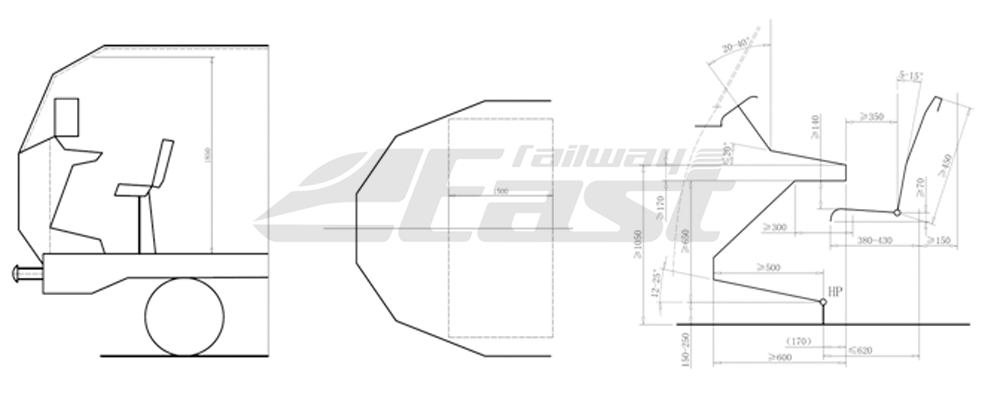
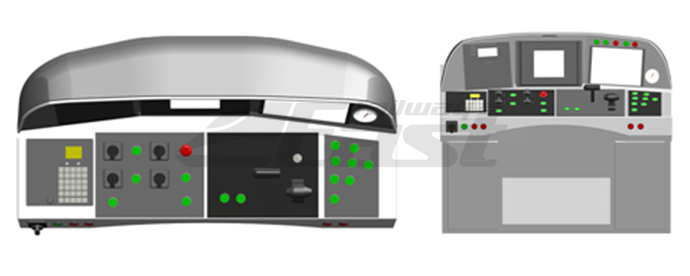
12. Internal size layout: Generally (Fig. 1), the height is not less than 1850mm, and the length is not less than 1500mm. If the user requests explicit requirements, the design is carried out according to user requirements.
figure1 figure 2
13.The recommended dimension of the driver desk and the seat (Figure 2)
14.driver desk main equipment and button switch name
No. | Function | Heading | Function introduction | Remark |
1 | Traction/Brake | Driver controller | Main control | Traction/brake integrated control |
Master key | Parking brake application | |||
Parking application | Parking brake relief | |||
Parking relief | Apply UB emergency brake | |||
Emergency brake (switch/brake) | Start front wheelset or all wheelset sanding | |||
Sanding (switch/button) | ||||
2 | Gating and lighting | Open the left door | Open all left door | |
Close the left door | Close all left door | |||
Release the left door | Left door release | |||
Release the right door | Right door release | |||
Open the right door | Open all right door | |||
Close the right door | Close allright door | |||
Headlight | Headlight glare/low light conversion | |||
3 | Wiper conversion | Wiper | Wiper function | |
4 | Sunshade control | Sunshade | Sunshade control | |
5 | Instrument、indicator | Control voltmeter | Display control voltmeter value | |
BP pressure gauge | Display BP tube pressure | |||
Double needle pressure gauge | Display train tube and total duct pressure | |||
6 |
High pressure system control |
VCB | Switch | |
Pantograph | Pantograph control | |||
7 | Warning | Fire alarm | Guest room fire alarm | |
Emergency alarm | Passenger emergency alarm | |||
8 | Vigilance device | DSD Manual Switch | Driver alert device | |
9 | Display | CIR Monitor | Monitor | |
CIR Microphone | Microphone | |||
CIR Printer | Printer | |||
ATP Display-1 | Display-1 | |||
ATP Display-2 | Display-2 | |||
TCMS Display-1 | Display-1 | |||
TCMS Display-2 | Standby TCMS Display | |||
10 | Bagpipe button | Bagpipe | Control the bagpipes | |
11 | Reset button | Reset | Reset traction converter and auxiliary power supply unit | |
12 | Emergency reset button | Emergency reset | Emergency brake (EB and UB safety loop) reset | |
13 | Cleaning brake button | Cleaning brake | Cleaning the brake disc | |
14 | Keep the brake button | Keep braking | Used for slopes when rolling up the slope | |
15 | Proportional brake button |
Proportional braking |
Proportional braking effective state | |
16 | Over-phase button | Manual over-phase | Manual over-phase |
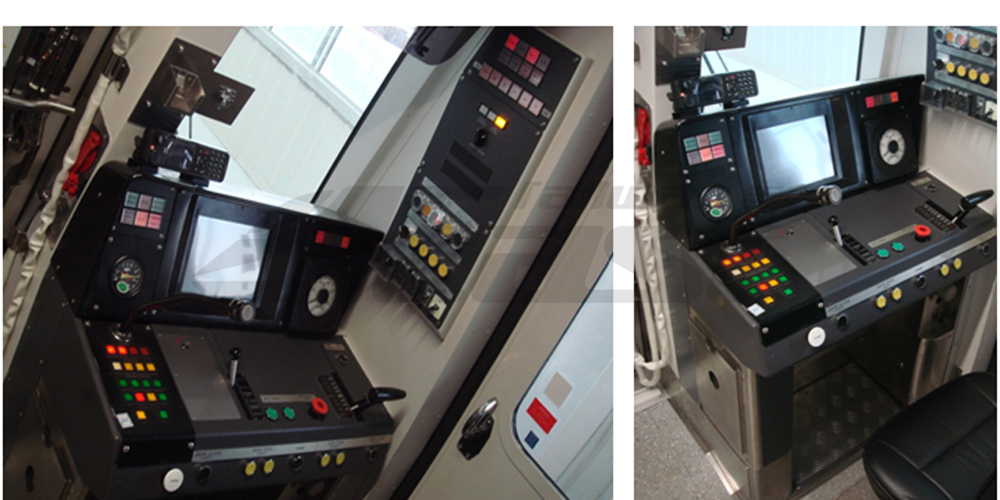
Reference solution 1
Reference solution 2